
Imagine you spend 18 hours printing a delicate ceramic part, only to watch it snap in half the moment you pick it up. For most researchers working with DLP 3D printing of technical ceramics, that frustration is all too familiar. The print looks flawless on the outside, yet the green body hides invisible weaknesses that no post-processing step can rescue.
Why does this happen, and what can you actually do about it?
A new study published in Ceramics International by Keqiang Zhang, Qiaoyu Meng, Zhaoliang Qu, and Rujie He at Nanjing Tech University and the Beijing Institute of Technology tackles exactly this problem. The team ran a controlled set of experiments on alumina (Al2O3) green bodies and looked at how three process parameters — slicing thickness, exposure time, and building direction — interact to determine mechanical performance. The findings are practical, immediately usable, and worth a careful read if you work in ceramic additive manufacturing.
In this article, we walk through the study step by step. We explain what the researchers did, what they found, and how you can apply their insights to your own work. Whether you design scaffolds for bone regeneration or thermal-protection parts for hypersonic vehicles, the lessons translate directly.
Why DLP 3D Printing Matters for Technical Ceramics
DLP 3D printing belongs to a broader family called vat photopolymerization (VPP). In simple terms, you pour a photosensitive ceramic slurry into a vat, then shine patterned UV light onto it layer by layer. Each flash of light cures a thin slice of the slurry, locking the ceramic particles in place. The platform lifts, a new layer of slurry flows underneath, and the process repeats — hundreds or thousands of times — until the part is complete.
The result is a “green body”: a fragile, polymer-bonded ceramic part that still needs debinding and sintering before it becomes a fully functional ceramic. Yet the green body sets the ceiling for everything that follows. If the green body contains cracks, weak interlayer bonds, or uneven curing, those flaws will only get worse after the binder burns out and the part densifies in the furnace.
This is why researchers have spent the last decade pushing DLP 3D printing of ceramics to higher and higher levels of quality. Alumina, in particular, sees heavy use in electronics, aerospace, biomedical implants, and wear-resistant parts. Getting the green body right means the difference between a sintered part that meets spec and one that fails quality control.
The Hidden Challenge in Vat Photopolymerization
Most studies in the field have looked at one parameter at a time. A research group might test exposure time, then publish their result. Another might focus on slicing thickness. Yet the printer in your lab runs all three variables together, and they interact in ways that no single-factor study can capture.
Take exposure time and slicing thickness. If you print with a thick layer but a short exposure, you may under-cure the resin at the interface. If you print with a thin layer but a long exposure, you waste hours of machine time on a strength gain that does not exist. The same uncertainty applies to building direction. A lattice tower printed in one orientation may break at half the load of the same tower printed in another orientation — even though the geometry is identical.
In short, the ceramic 3D printing community needs a systematic map of how these variables combine. That is the gap Zhang and his colleagues set out to fill.
What the Study Set Out to Do
The team prepared a photosensitive Al2O3 slurry with a median particle size of about 10.34 μm and used a DLP printer capable of slicing at 25, 50, or 75 μm. They then designed a series of three-point bending tests to measure the flexural strength of the resulting green bodies, and they used scanning electron microscopy (SEM) to study the fracture surfaces.
They varied one parameter at a time, but they chose the test conditions carefully so the results would tell a coherent story:
- Slicing thickness study: 25 μm, 50 μm, 75 μm (fixed exposure time of 14 s, Z-direction build).
- Exposure time study: 7 s, 14 s, 21 s (fixed slicing thickness of 25 μm, Z-direction build).
- Building direction study: X, Y, Z (fixed slicing thickness of 25 μm, exposure time of 7 s — a deliberately sensitive test condition).
Let us look at each finding in turn.
How Slicing Thickness Affects Al2O3 Green Body Strength
It feels intuitive that thinner layers should give you stronger parts. After all, you are stacking more layers, and each interface is a chance for a defect. Yet the data from this study tells a more interesting story.
The researchers printed green bodies at three layer thicknesses while keeping exposure time and build direction constant. The flexural strength of the green body at 25 μm and 50 μm was essentially the same, around 15 MPa. Once they pushed the slicing thickness to 75 μm, however, the strength dropped sharply to about 10.65 MPa.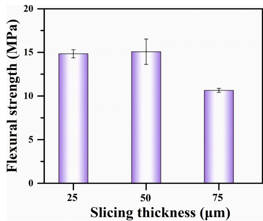
Fig. 1 — Flexural strength of the Al2O3 green bodies as a function of slicing thickness. Note how the 50 μm condition matches the 25 μm result, while the 75 μm condition falls sharply. (Reprinted from Zhang et al., Ceramics International 52 (2026) 8464–8470, with permission from Elsevier.)
What is going on here? The UV light in a DLP printer has a fixed penetration depth at a given exposure time. When the layer is thinner than this depth, the resin cures through the entire slice and bonds well to the layer below. When the layer is thicker than the cure depth, the bottom of the new layer does not fully polymerize, and the bond to the previous layer weakens. At 50 μm, the layer still fits within the cure envelope, so strength holds up. At 75 μm, you start to see incomplete polymerization at the interface, and cracks form between layers.
The SEM images make this damage visible. At 25 μm and 50 μm, the fracture surface shows a relatively uniform resin matrix with Al2O3 particles embedded throughout. At 75 μm, however, you can see continuous cracks running along the layer interfaces — a classic sign of under-cured bonding.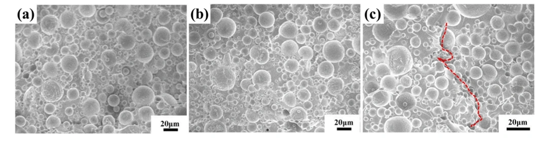
Fig. 2 — SEM images of the fracture surface at different slicing thicknesses: (a) 25 μm, (b) 50 μm, and (c) 75 μm. The red arrow in (c) marks the continuous interlayer crack that forms when the layer exceeds the UV cure depth. (Reprinted from Zhang et al., Ceramics International 52 (2026) 8464–8470, with permission from Elsevier.)
For practical purposes, this result is excellent news. You do not have to push your printer to its thinnest setting to get the strongest possible part. A slicing thickness of 50 μm gives you essentially the same green body strength as 25 μm, but you cut your print time roughly in half. When you are running a tight experimental schedule, those hours matter.
The Role of Exposure Time in DLP 3D Printing
The next variable the team explored was exposure time. This parameter controls how long the UV light shines on each layer, and it directly determines how much of the photosensitive resin polymerizes.
They tested 7 s, 14 s, and 21 s, holding slicing thickness at 25 μm and building direction along Z. The results show a clear, monotonic trend. At 7 s, the green body flexural strength measured about 11.67 MPa. At 14 s, it rose to around 16.61 MPa, and at 21 s, it stayed in a similar range. In other words, doubling the exposure from 7 s to 14 s nearly doubles the green body strength.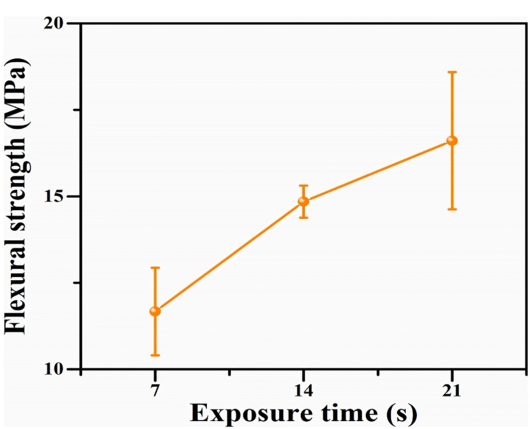
Fig. 3 — Flexural strength as a function of exposure time. Longer exposure drives stronger curing, which translates into a stronger green body. (Reprinted from Zhang et al., Ceramics International 52 (2026) 8464–8470, with permission from Elsevier.)
Why does exposure time matter so much? The strength of the green body comes primarily from the cured resin matrix that binds the Al2O3 particles together. If the resin does not polymerize fully, the matrix stays soft, and the part fails at low stress. When you extend the exposure, more of the resin reaches a high conversion, and the matrix becomes stiffer and stronger.
The SEM evidence supports this. At 7 s, the fracture surface shows multiple cracks running through the resin matrix, a sign that the matrix itself is the weak link. At 14 s and 21 s, the matrix holds together better, and you see more pits where Al2O3 particles have pulled out of the matrix — a sign that the resin has actually become stronger than the particle–matrix interface.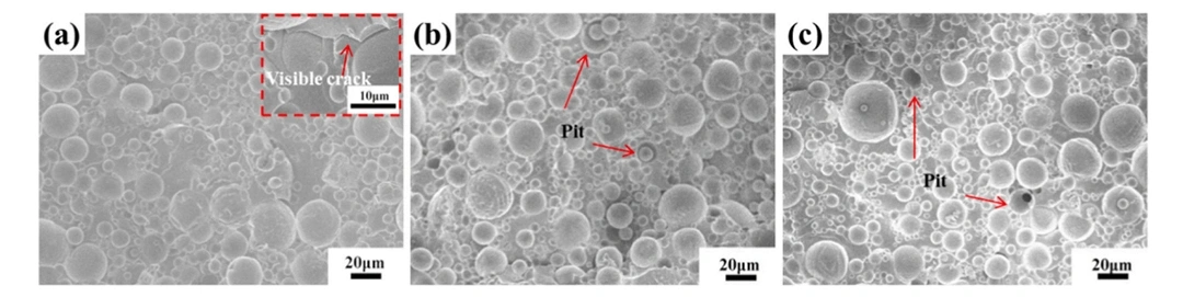
Fig. 4 — SEM images of the fracture surface at different exposure times: (a) 7 s, (b) 14 s, and (c) 21 s. The arrows highlight visible cracks in the resin matrix at 7 s and the absence of such cracks at longer exposure times. (Reprinted from Zhang et al., Ceramics International 52 (2026) 8464–8470, with permission from Elsevier.)
A word of caution here, though. The paper notes that excessively long exposure can cause over-curing, leading to volumetric shrinkage, residual stress, and even cracking in the green body. The team did not push exposure time beyond 21 s, so you should treat the 21 s result as a near-optimum within their tested window. If you go further, you may run into new problems.
Building Direction — The Quietest but Most Critical Variable
Here is the finding that should change how you think about part orientation.
The researchers printed identical bending bars in three different orientations — X, Y, and Z — and tested them under three-point bending. The flexural strength values were dramatically different:
- X-direction: about 8.48 MPa (lowest)
- Z-direction: intermediate, around 10–11 MPa
- Y-direction: about 13.66 MPa (highest)
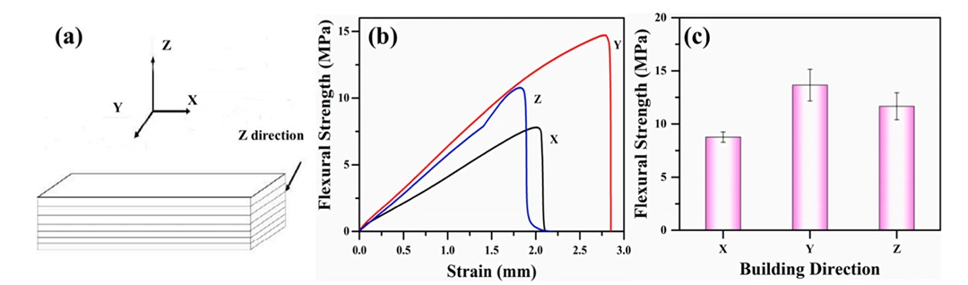 Fig. 5 — (a) Schematic of the X, Y, and Z building directions, (b) flexural strength–strain curves, and (c) maximum flexural strength for each direction. The Y-direction shows the steepest stress–strain curve and the highest peak strength. (Reprinted from Zhang et al., Ceramics International 52 (2026) 8464–8470, with permission from Elsevier.)
To put those numbers in context, the fracture energy for Y-direction green bodies measured 24.12 J/m², nearly three times the 8.81 J/m² measured for the X-direction. That is a huge difference for an orientation change that costs nothing in machine time.
Why does orientation matter so much? The answer lies in the layer-by-layer nature of DLP 3D printing. When the printer stacks a new cured layer on top of the previous one, it forms an interface between them. The bonding across that interface relies on secondary polymerization of unreacted resin groups, and it is always weaker than the material within a single layer. The interface is, in effect, a “preferred failure path” through the part.
Now think about what happens in a three-point bending test. The bottom of the bar stretches, the top compresses, and the maximum tensile stress sits on the outer fiber of the bottom face. If you build the bar along the X-direction, the layers run parallel to the loading direction. The tensile stress then pulls directly across the weak interlayer interfaces, and the bar delaminates easily. If you build the bar along the Y-direction, however, the layers run perpendicular to the loading direction. The tensile stress has to pull the material through the layer itself, not along the interface, and the bar resists the load much more effectively.
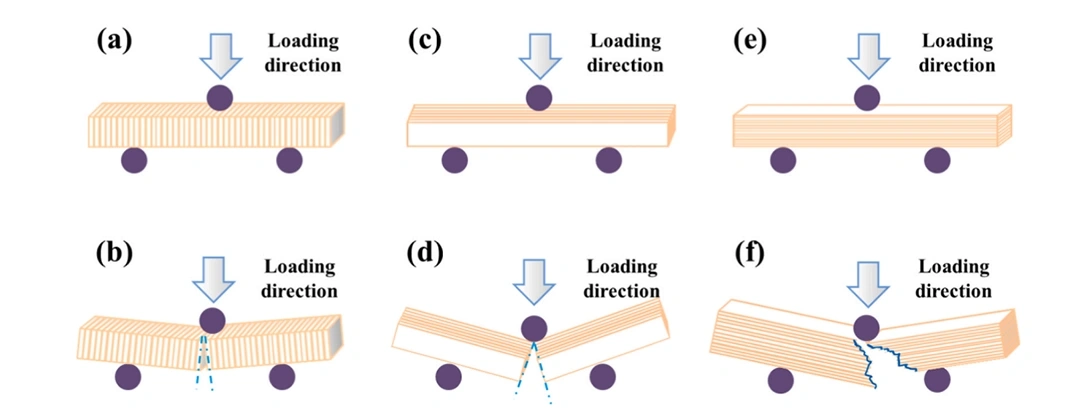
Fig. 6 — Schematic of the three-point bending test and the fracture mechanism in the X, Y, and Z directions. (a)(b) X-direction: cracks propagate along interlayer interfaces (lowest strength). (c)(d) Y-direction: cracks must cross the layer body (highest strength). (e)(f) Z-direction: a mixed mode with crack propagation along the interfaces but partial layer crossing. (Reprinted from Zhang et al., Ceramics International 52 (2026) 8464–8470, with permission from Elsevier.)
The SEM images confirm this fracture pattern. In the X-direction samples, the fracture surface is smooth — a tell-tale sign that the crack ran along an interface rather than through the matrix. In the Y-direction samples, the surface is rough, with multiple cracks inside the resin matrix and along the layers, indicating that the crack had to do real work to advance. In the Z-direction samples, the surface looks like a mix of both.
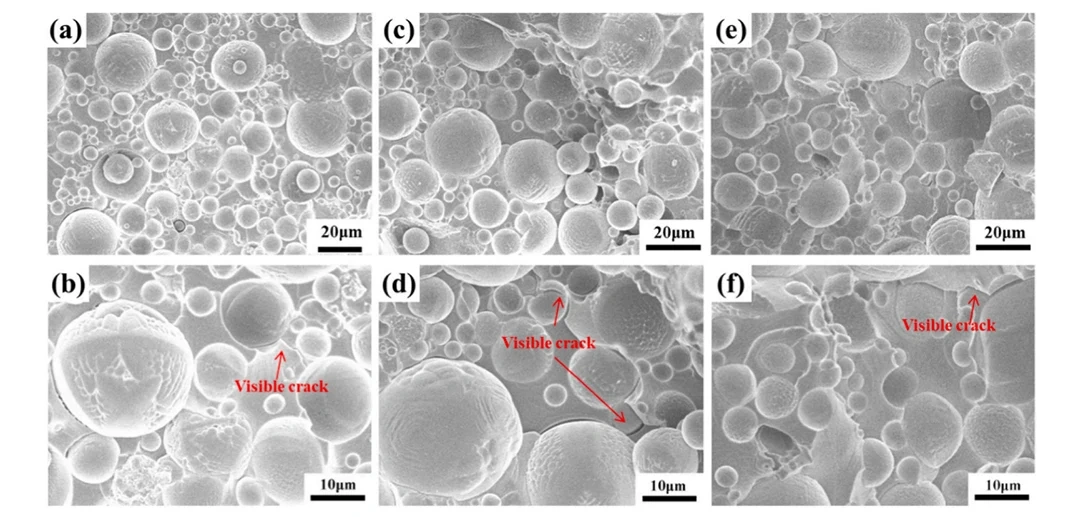
Fig. 7 — SEM images of the fracture surface for the three building directions. (a)(b) X, (c)(d) Y, (e)(f) Z. The Y-direction samples show extensive crack branching and a rough surface, while the X-direction samples show a relatively smooth surface. (Reprinted from Zhang et al., Ceramics International 52 (2026) 8464–8470, with permission from Elsevier.)
One subtle but important note: the team ran the building-direction study at a relatively short exposure time of 7 s. They chose this condition deliberately. At short exposure times, interlayer bonding is weaker, so the role of the weak interfaces becomes easier to see. At longer exposure times, the matrix grows stronger, and the gap between directions narrows. The directional effect is real, but its magnitude depends on how well the resin cures in the first place.
Putting It All Together: From Parameters to Complex Parts
So what is the practical recipe that comes out of this study? The researchers recommend the following set of process parameters for Al2O3 green bodies in their DLP system:
- Slicing thickness: 50 μm (good strength, fast cycle time)
- Exposure time: 14 s (good polymerization, no obvious over-cure)
- Building direction: Y (highest flexural strength, best resistance to delamination)
With these parameters locked in, the team printed three challenging geometries to confirm the approach: a skeletal bone-like structure, a load-bearing lattice, and a set of small Eiffel Tower shapes.
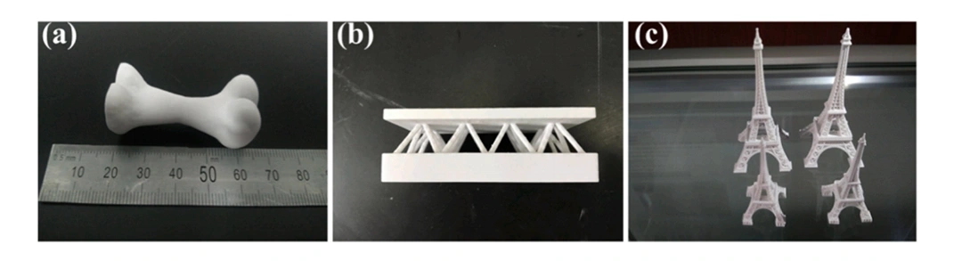
Fig. 8 — DLP 3D printed Al2O3 green bodies with optimized process parameters: (a) a skeletal structure, (b) a load-bearing lattice, and (c) Eiffel Tower shapes. These complex geometries demonstrate that the optimized parameters work for real-world designs, not just simple test bars. (Reprinted from Zhang et al., Ceramics International 52 (2026) 8464–8470, with permission from Elsevier.)
All three parts printed successfully, and they held their shape through handling. That matters because the whole point of DLP 3D printing is to make complex shapes that other processes cannot produce. If your optimized parameters only work on bending bars, they are not really optimized.
What This Means for Your Research
The study has three practical lessons that you can apply directly to your own work, regardless of the specific ceramic material you use.
First, do not assume thinner is always better. The result on slicing thickness is counter-intuitive but robust. A 50 μm layer gives you nearly the same strength as a 25 μm layer, and you save a lot of time. Run a small test on your own material and slurry before committing to the thinnest setting your printer offers.
Second, respect the exposure time. A short exposure is one of the fastest ways to ruin a print. If you are chasing strength in the green body — and you should be, because green body flaws become ceramic flaws after sintering — push your exposure time up to the point where the resin fully cures, but stop before you start to see over-cure defects like cracks or excessive shrinkage.
Third, think about orientation as a design variable, not a printer setting. For load-bearing parts, the difference between X-direction and Y-direction builds can be a factor of two or more in flexural strength. When you design a ceramic component for DLP 3D printing, ask yourself: which way will the load run, and which way will the layers run? Those two directions should be perpendicular for maximum strength.
If you are new to DLP 3D printing of ceramics, you may also want to explore the wider literature on vat photopolymerization. Several recent reviews offer a good overview of the field, including Chen et al. on 3D printing of ceramics and Lakhdar et al. on additive manufacturing of advanced ceramic materials. The Zhang team’s own review of defects in vat photopolymerization ceramics is also a useful companion to this paper.
Final Thoughts and What’s Next
The systematic insight from Zhang and colleagues is a welcome addition to the ceramic 3D printing literature. It pulls together three parameters that researchers usually study in isolation and shows how they interact in a real DLP workflow. The 50 μm / 14 s / Y-direction recipe is a strong starting point for Al2O3, and the methodology generalizes naturally to other ceramics such as zirconia and silicon carbide.
There is one important caveat. The team measured the strength of the green body, not the sintered ceramic. The next step — and the authors flag this as future work — is to study how these parameters carry through debinding and sintering. Some green body flaws disappear during densification, and some get worse. The interaction between printing parameters and sintering behavior is the next piece of the puzzle.
For now, if you are struggling with weak or unreliable DLP 3D printed ceramic parts, start with the three parameters covered in this study. Run a small design of experiments on your own slurry, measure the flexural strength, and look at your fracture surfaces under SEM. The patterns you see will likely echo the findings above, and the time you invest in optimization will pay back many times over in stronger, more reliable ceramic components.
References
- Zhang, K., Meng, Q., Qu, Z., & He, R. (2026). A systematic insight into the DLP process of additive manufactured Al2O3 ceramic green body. Ceramics International, 52, 8464–8470. https://doi.org/10.1016/j.ceramint.2026.01.043
- Chen, Z., Li, Z., Li, J., et al. (2019). 3D printing of ceramics: A review. Journal of the European Ceramic Society, 39(4), 661–687.
- Lakhdar, Y., Tuck, C., Binner, J., et al. (2021). Additive manufacturing of advanced ceramic materials. Progress in Materials Science, 116, 100736.
- Zhang, K., Meng, Q., Qu, Z., et al. (2024). A review of defects in vat photopolymerization additive-manufactured ceramics: Characterization, control, and challenges. Journal of the European Ceramic Society, 44(3), 1361–1384.