
Lead-free piezoelectric ceramics are printable. What has been hard to print is a part that also performs like a pressed one — and a part that does something a pressed one cannot. Those two goals pull in opposite directions, and a 2026 paper in Advanced Functional Materials from Harbin Institute of Technology's Centre for Composite Materials and Structures (with the School of Aerospace Engineering and Mechanics and the Suzhou Research Institute) attacks both at once.
The short version: a BaTiO₃ slurry at 90 wt.% solids was printed into triply periodic minimal surface (TPMS) lattices whose X, Y and Z periods are scaled independently. Because the poling direction stays fixed while the mechanical response does not, a single monolithic part ends up with a different sensitivity along each axis — three-axis force discrimination without an array of sensors.
That is the headline. The more useful material for anyone printing ceramics is in the middle: what 90 wt.% actually costs, and why the highest solid loading turns out not to be the best sensor.
1. The three-way conflict
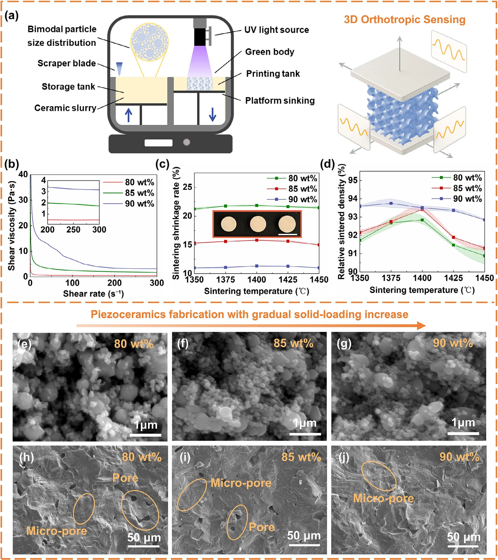
The literature consensus is easy to state. Ceramic vat photopolymerisation formulations cluster around 80 wt.% solids (roughly 40 vol.%), which typically delivers d₃₃ near 200 pC N⁻¹ and compressive strength around 250 MPa. Going higher is where it breaks: rheological instability and defect accumulation create a performance inflection around 80 wt.%, and past that threshold the extra solids buy you porosity defects rather than density, hurting accuracy, electrical properties and strength at the same time.
So three requirements fight each other. Solid loading sets the piezoelectric coefficient, because porosity dilutes it. Viscosity sets the printable precision, and it climbs steeply with solids. And sintering decides whether the green body survives at all — at 80 wt.% the linear shrinkage is 21.50%, which distorts thin features on the way to dense.
The paper's claim is that all three can be improved together, not traded off. The lever is particle packing.
2. What 90 wt.% takes
The powder was used bimodal: fine particles with d₅₀ = 104.40 nm, blended with coarser ones at a fine-to-coarse ratio of 4 to 6. Small particles fill the gaps between large ones, so the same flow behaviour is reached at a higher solids fraction. The 90 wt.% slurry — over 62 vol.% — stayed shear-thinning through the whole curve, and at high shear its viscosity dropped to 3.22 Pa·s (against 0.48 and 1.88 Pa·s for 80 and 85 wt.%). Under the blade, that shear thinning is what flattens the layer and bonds it to the one below.
Two consequences show up downstream. Linear shrinkage fell from 21.50% at 80 wt.% to 11.00% at 90 wt.%, and the peak relative density reached 93.75%. Lower shrinkage is not a cosmetic gain: it is the difference between a 110 µm strut that stays 110 µm and one that collapses into its neighbour.
Green bodies were printed on a dual-vat sinking-type DLP system (ADT-3D-ZP-Printer-96-50, AdventureTech) at 30 µm layers, 5 s exposure and 58 mW cm⁻² at 405 nm, then debound in two stages — argon to 500 °C to carbonise the organics, air to 500 °C to burn off the carbon — and sintered in air at 2 °C min⁻¹ with a 2 h dwell.
3. The numbers, against dry-pressed
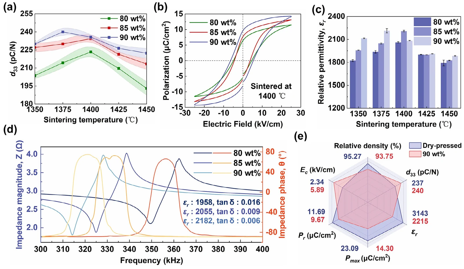
The 90 wt.% ceramic sintered at 1375 °C — its own optimum — reached d₃₃ = 240 ± 3 pC N⁻¹, relative permittivity 2215 ± 27 and dielectric loss 0.006, with a compressive strength of 342 ± 6 MPa. That last number sits well above the ~250 MPa reported for other DLP-printed BaTiO₃, and the d₃₃ lands within a whisker of the dry-pressed reference (240 against 237).
The honest comparison is the radar plot, not the headline. Dry-pressed still wins on permittivity (3143 vs 2215), remnant polarisation (23.09 vs 14.30 µC cm⁻²) and ease of switching (coercive field 2.34 vs 5.89 kV cm⁻²), while the printed body matches on d₃₃ and gives up a point of relative density (93.75 vs 95.27). The authors read the higher coercive field as a positive — a denser body needs more energy to switch its domains, which they frame as stability under high field — and their own note explains where it comes from: porosity suppresses the depolarisation field, so removing porosity raises the switching field. Printing buys architecture; it pays for it in polarisation.
4. Where the precision actually lands
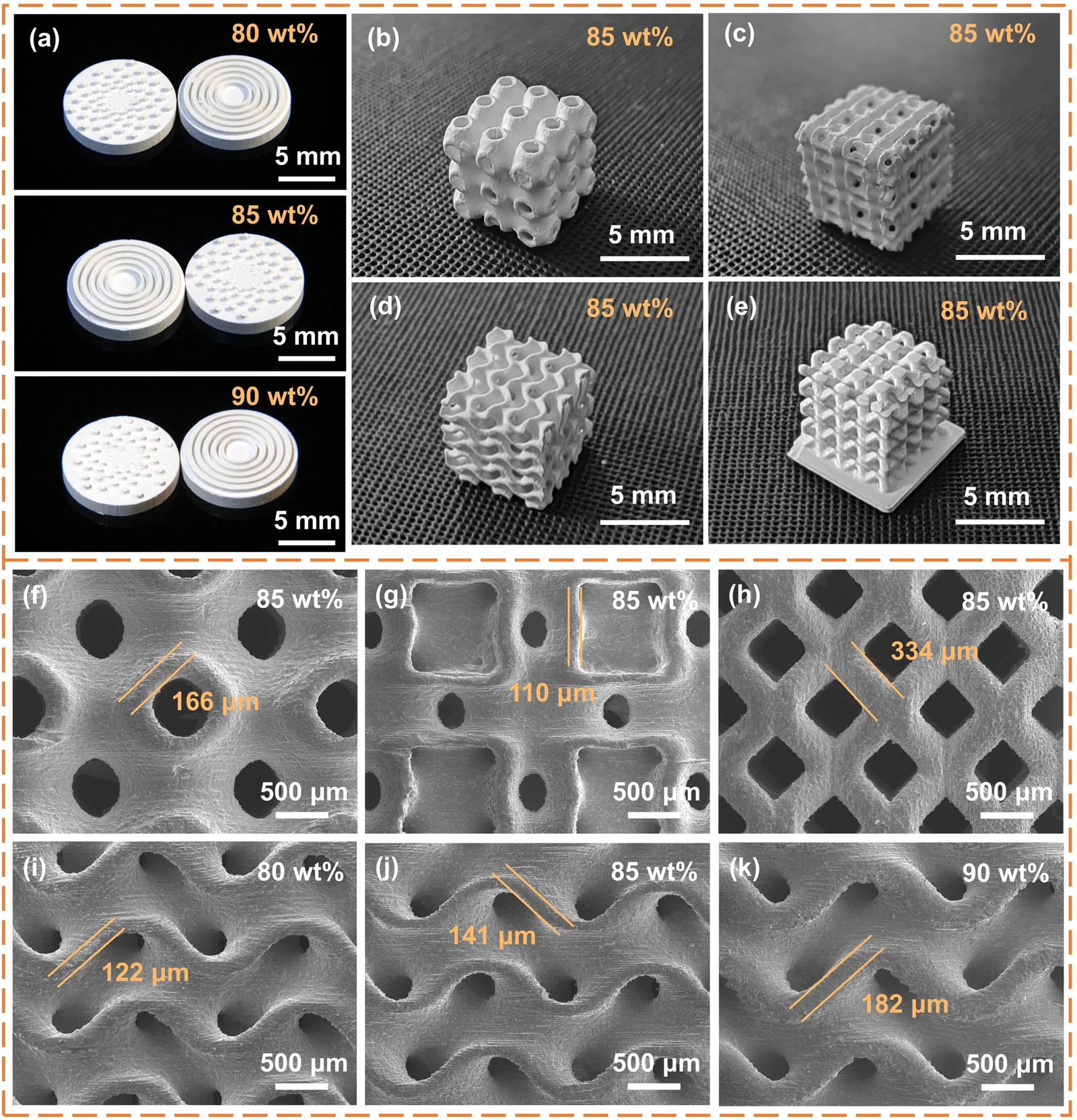
Resolution claims are cheap, so the paper measures struts. Three TPMS families were printed — Primitive, I-WP and Gyroid — plus a BCC lattice, with unit cells of 2 mm and 1.5 mm respectively — and the sintered features came in between 110 and 334 µm: 110 µm for the I-WP strut, 166 µm for Primitive, 334 µm for the BCC diamond, and 122 to 182 µm across the Gyroid row depending on solid loading. Devices are under 5 mm on a side with sub-200 µm critical features.
Two details matter more than the range. First, thin walls converge and free-standing columns do not: every formulation printed 100 µm walls, but the columns separate — 80 wt.% holds 150 µm and only partially collapses at 100 µm, while 85 and 90 wt.% stop at 200 µm with partial success at 150 µm. The highest solid loading is the least capable at fine columns, not the most.
Second, the same designed Gyroid sintered to 122 µm walls at 80 wt.%, 141 µm at 85 wt.% and 182 µm at 90 wt.%. The authors attribute that to shrinkage and light scattering: the 80 wt.% body shrinks 21.50% against 11.00%, so it thins further on the way to dense. The designed wall is not the printed wall, and that gap is what explains section 7.
5. Programming the anisotropy
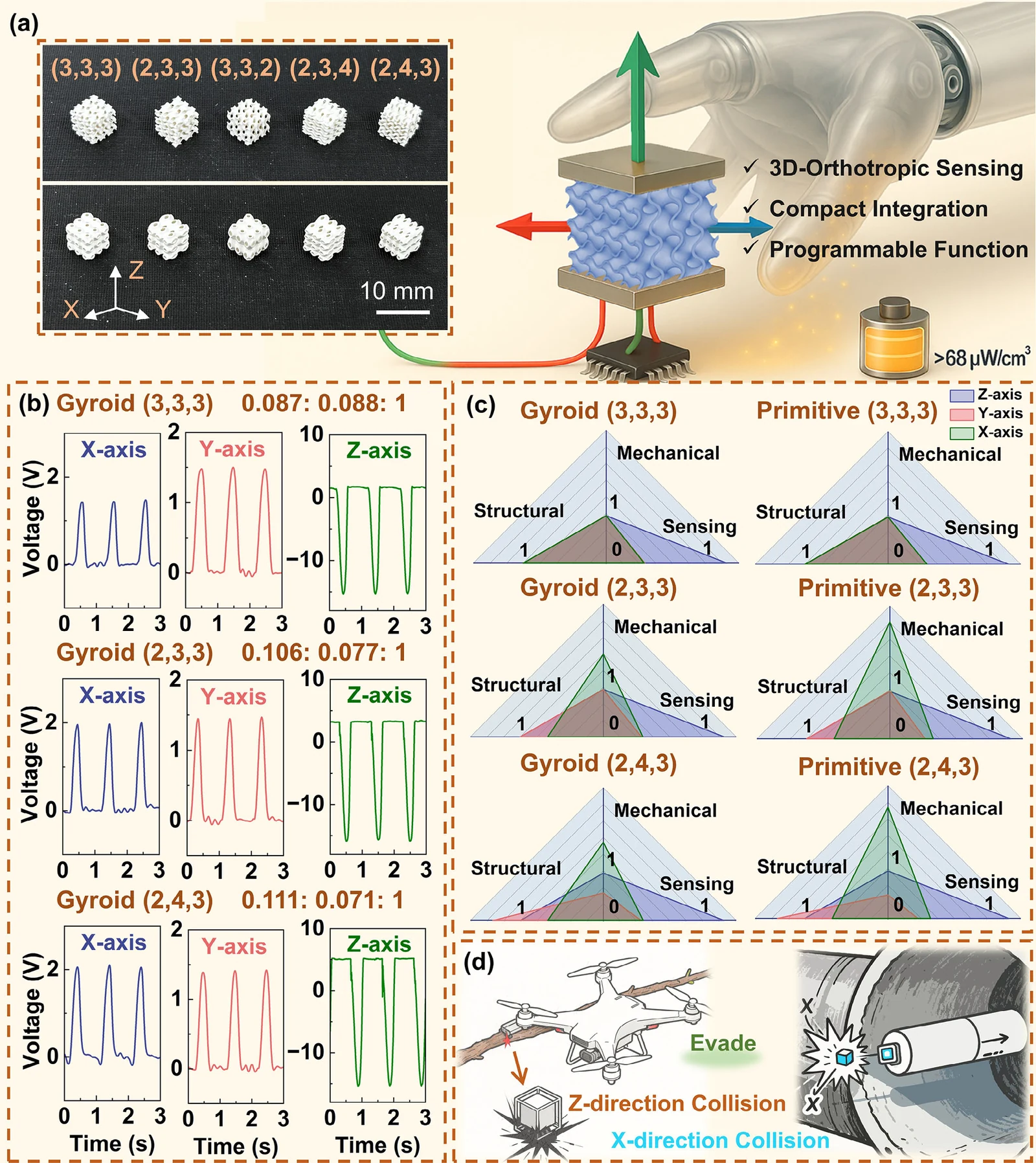
This is the part worth stealing. A TPMS cell carries three independent scaling parameters — a, b and c — that set the spatial period along X, Y and Z. The labels on the figure are unit-cell counts rather than the periods themselves: m = 3a/λ, so (2,3,3) means two cells along X against three along Y and Z, a coarser period in X. Scale all three together and the lattice is mechanically isotropic; detune them and the symmetry breaks in a controlled hierarchy, from uniaxial (a = b ≠ c) to fully orthotropic (a ≠ b ≠ c).
Now hold the poling direction fixed along Z. Charge depends on how the strain field couples into the poled axis, and the strain field is no longer direction-independent, so the sensitivity gradient is built into the geometry rather than added by extra sensors. The sharpest theoretical point in the paper sits here: the sensing anisotropy can carry more dimensions than the mechanical one. A structure that is only uniaxially anisotropic in mechanics can still resolve three axes, because stress from each direction couples into the Z axis with a different efficiency. The Gyroid adds a lever the Primitive lattice does not have — its triple-helical, chiral geometry carries an inherent handedness.
The ratios printed above each panel — every one normalised to the Z axis — bear that out: 0.087 : 0.088 : 1 for the (3,3,3) Gyroid, still symmetric in X and Y; 0.106 : 0.077 : 1 for (2,3,3); 0.111 : 0.071 : 1 for (2,4,3), where the two in-plane axes have separated by more than 50%.
Two demos make the consequence concrete: a micro-drone that tells a side impact from a frontal one, and contact sensing for vision-denied spaces — debris fields and confined pipes — where a camera has nothing to work with. One printed part does the job that would otherwise take an array.
6. Speed, linearity, and harvesting
One thing to keep straight before the numbers: these are not bare ceramic coupons. The Gyroid lattices are cast in epoxy and then poled, so what is measured is a ceramic–epoxy lattice composite — which is why the paper calls it an "80 wt.% composite sensor". The 240 pC N⁻¹ in section 3 belongs to a solid pellet; the sensing figures below belong to the composite structure.
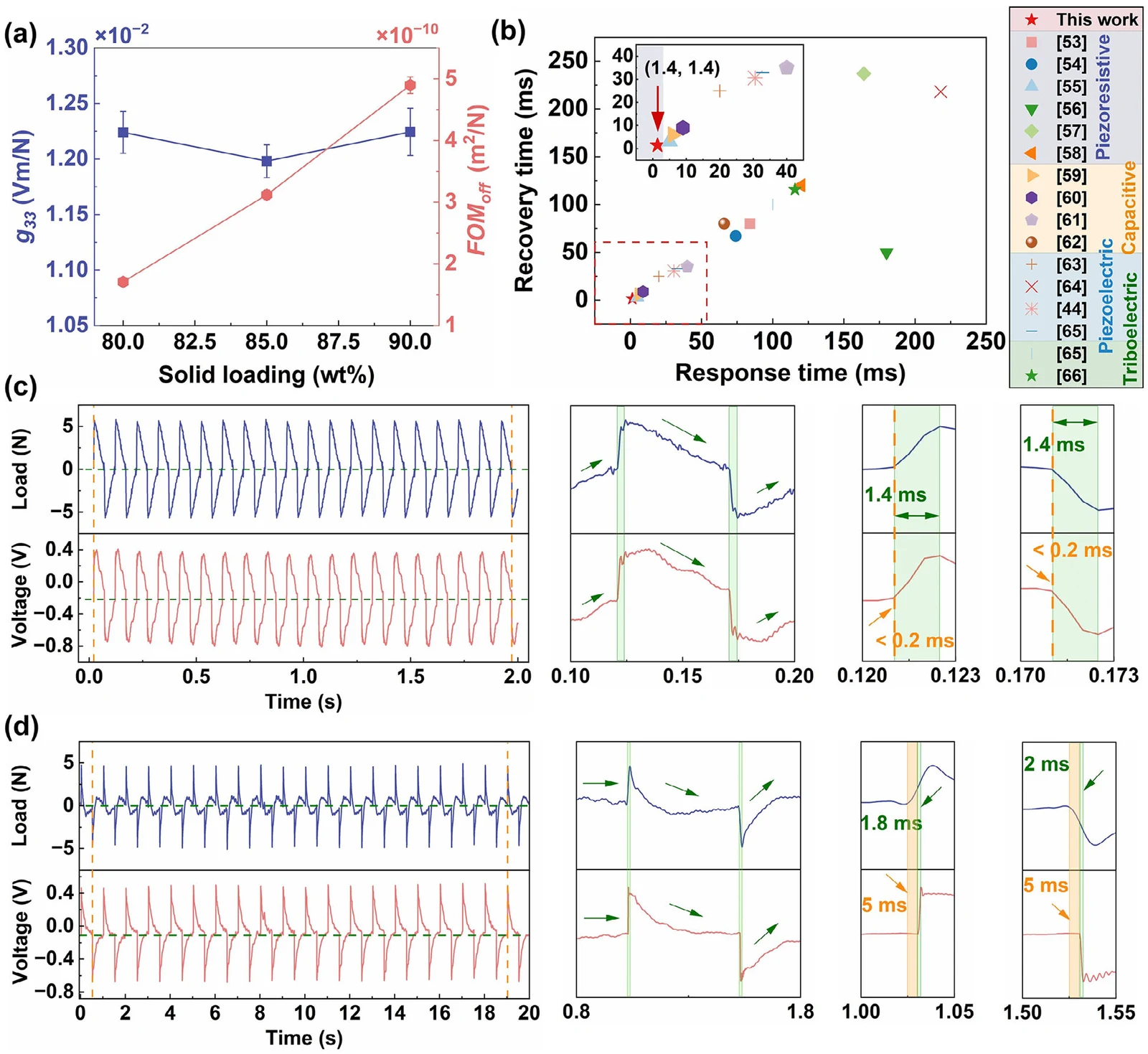
The dynamic behaviour is better than the sensitivity figure suggests. Under 10 Hz cyclic loading, mechanical and electrical signals stayed synchronised to within 1.4 ms, with a delay under 0.2 ms — competitive with capacitive, resistive and triboelectric tactile sensors, which is a striking result for a cast lattice.
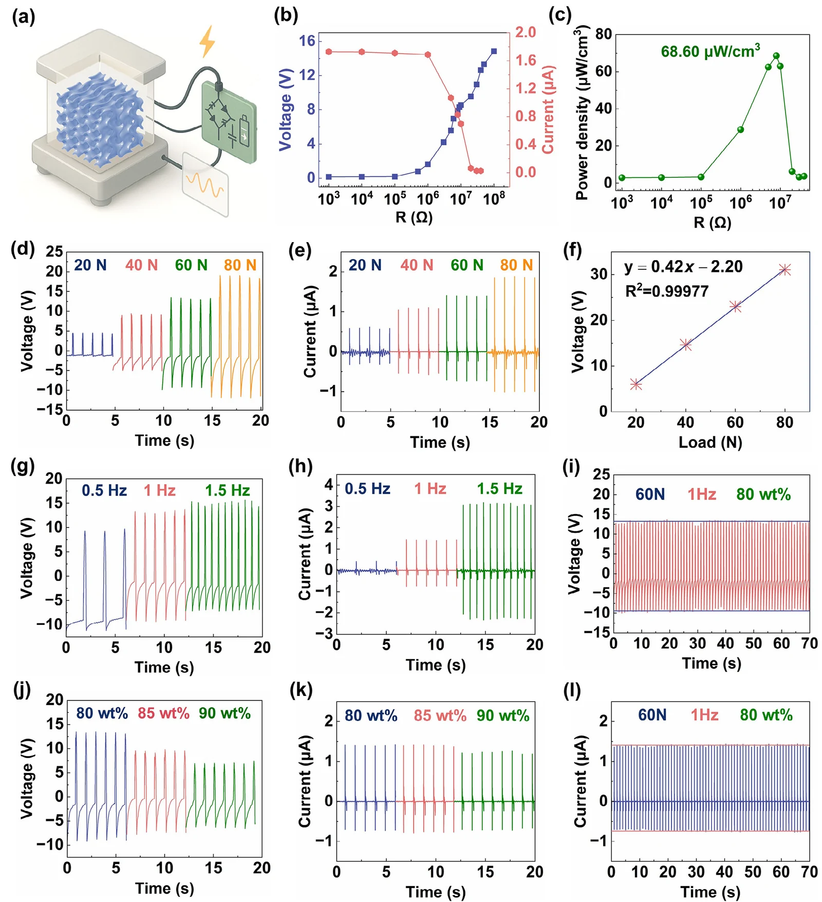
Force response was 0.42 V N⁻¹ with R² = 0.99977 across 20–80 N, and about 3 µA at 80 N. Voltage barely moves with frequency, but current does, because I scales linearly with f under a given load — so the same device reads force from voltage and frequency from current.
Run as a harvester under 40 N impulses at 1 Hz, power density peaked at 68.60 µW cm⁻³ into 8 MΩ. The authors also deployed it as a wireless gait sensor and used it to separate static from dynamic gait patterns.
7. The trade-off the abstract does not mention
Here is the sentence that matters most for process people: the 90 wt.% variant was less sensitive than the 80 wt.% sample. The cause is the wall thickness from section 4 — 182 µm against 122 µm. The authors put it down to charge-collection efficiency: in a thicker wall the charge generated through the volume has further to travel to reach an electrode, and that loss outweighs the d₃₃ gain.
So the paper contains a real trade-off, not a free lunch. 90 wt.% is the best structural and piezoelectric material; 80 wt.% is the best sensor. The 0.42 V N⁻¹, 1.4 ms and 68.60 µW cm⁻³ figures all come from the 80 wt.% build, while the 240 pC N⁻¹ and 342 MPa figures come from the 90 wt.% one. No single build in this study was optimised for both.
8. What the study does not show
- No single optimised device. Mechanical and sensing performance are champion values from different solid loadings, so the radar plot is a portfolio, not a part.
- Multi-axis loading is never tested. Every reported test applies force along one axis, so the three-axis claim rests on single-axis calibration; how the channels behave under a simultaneous or off-axis load — the situation the application actually presents — is not measured.
- Read-out is left to the supplement. Three channels — X, Y and Z — means electrodes on more than one face, but how the pairs are arranged and how much they interfere sits in Section S5.6. The axial tests also needed the electrodes reversed to present positive polarity, which is a useful reminder that wiring is not neutral in this device.
- The cycling test is short. Stability is 70 s at 1 Hz, roughly 70 cycles. Piezoelectric ceramics are usually judged over 10⁵–10⁶ cycles, and mechanical fatigue of a 110 µm lattice is a separate question.
- Geometry and mass move together. Changing the periods changes stiffness, wall thickness and resonant behaviour at once; the paper treats the combination as one design variable and does not separate which effect drives the sensitivity split.
- BaTiO₃ only. The framework should transfer to PZT or KNN systems, but d₃₃ = 240 pC N⁻¹ is modest against soft PZT, and nothing here tests another chemistry.
- Yield stays qualitative. Partial collapse at 100–150 µm columns is reported honestly, but not how many parts survive a build — the number that decides whether a process is a process.
9. What it means for ceramic printing
Two things hold up. First, 90 wt.% BaTiO₃ is printable — not in a paragraph of claims but as 110 µm sintered struts, 11% shrinkage and 93.75% density. Bimodal packing is the mechanism, and it is available to anyone with a mill and a rheometer.
Second, geometry is now a sensing parameter. Once the period scaling sets the axis response, the design file is doing electromechanical work, and it needs the same discipline as the formulation. That is a very different role for a printer than "make the shape"; it requires the machine to hold 30 µm layers evenly across the whole build area, because a wall that prints 20 µm thicker in one corner than another changes the sensitivity ratio the design leans on.
In this study that machine was a dual-vat DLP system, the ADT Ceram-D-L96 (published as ADT-3D-ZP-Printer-96-50): 96 × 54 mm build area, 50 µm optical precision, 405 nm, running at 58 mW cm⁻².
Source: Wang P, Sun Y, Zhao W, Lan X, Liu Y, Leng J. Programmable 3D-Orthotropic Piezoceramic Sensors Enabled by Solid-Loading-Maximized Additive Manufacturing. Advanced Functional Materials (2026). doi:10.1002/adfm.202523909. Figures reproduced from the cited article for discussion.