
Reaction-bonded silicon carbide (RBSC) is the workhorse SiC route: a porous carbon-rich preform is infiltrated with molten silicon, which reacts in place to form secondary SiC. It densifies at far lower temperatures than solid-state sintering, holds near-net shape, and reaches full density. Pair it with DLP printing and you can make complex, high-resolution SiC parts — mirrors, semiconductor equipment components, thermal structures — without years of machining.
But the combination has a stubborn ceiling. SiC powder absorbs and scatters UV strongly, so SiC slurries cure shallow and print poorly. And the carbon source that drives reaction sintering fights the slurry: phenolic resins shrink and lose mass during pyrolysis, while carbon black and graphite are so UV-absorbing that they kill curing depth altogether. Most published DLP/RBSC work also ends up with 10–20 vol% of leftover silicon — a soft, low-strength phase that acts as a crack path.
A study published in Additive Manufacturing (2026) attacked both problems with one material choice — submicron diamond — and then did something less common: it engineered the residual stress distribution itself. The result, printed on an ADT DLP system, was RBSC at 452.4 MPa flexural strength, 43.56 GPa Vickers hardness, 3.14 g/cm³ density and only 7.8 vol% residue silicon, with a compressive "armor" layer at the surface that works the same way chemically tempered glass does.
1. The setup: nine slurries, one printer
The team, from the Institute of Structured and Architected Materials (Liaoning Academy of Materials, Shenyang) with a co-author from Shenzhen Adventure Technology, built nine slurry formulations (SP1–SP9) varying SiC loading (34.34–39.68 vol%) and diamond loading (8.60–11.32 vol%) in an HDDA/TMPTA resin. The diamond was fine — D50 = 0.73 µm against D50 = 11.87 µm for the SiC powder — and that size ratio turns out to matter everywhere downstream.
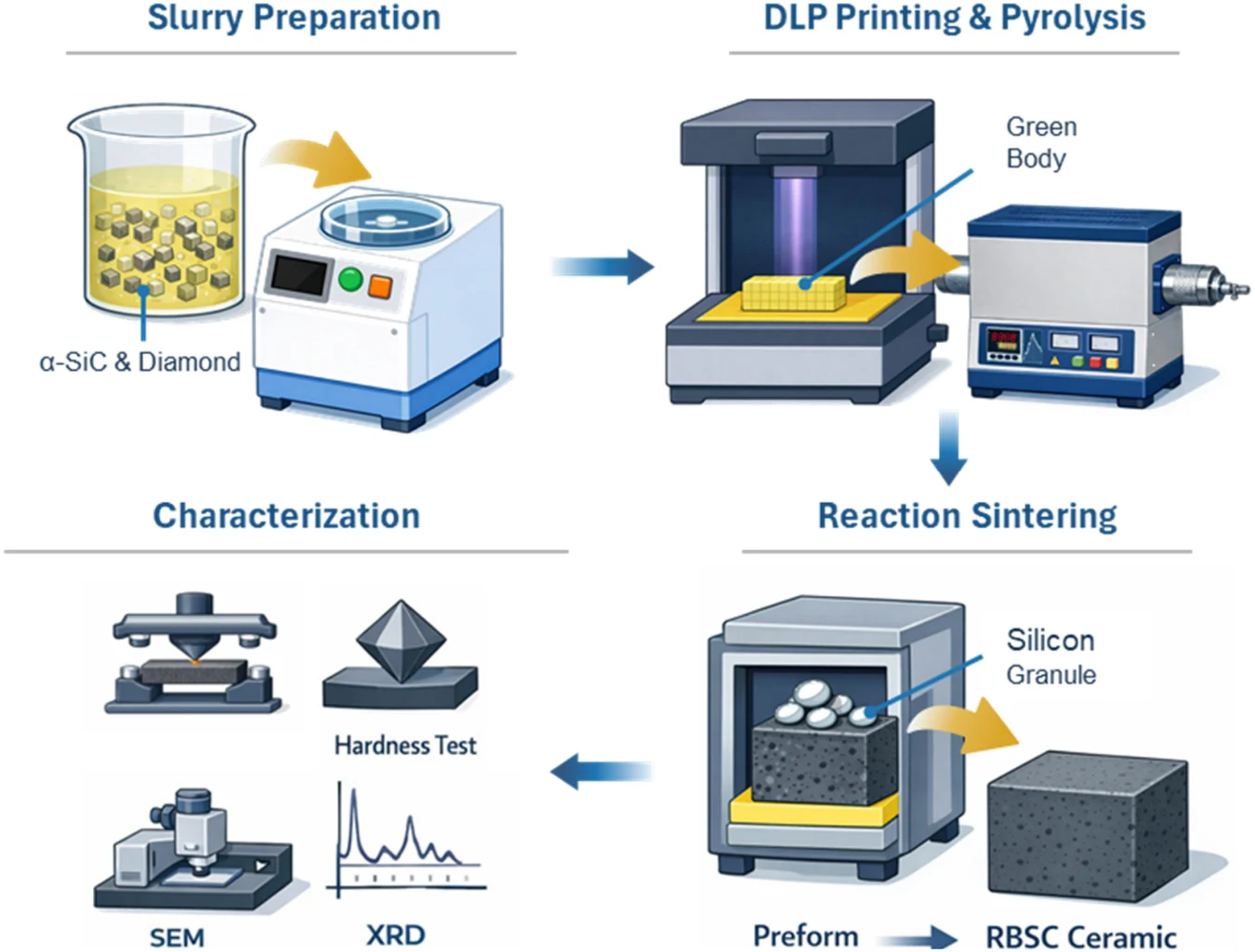
Printing ran on a commercial ADT DLP ceramic printer (Adventure-3D-ZP-Printer-Pro-192×50 — the ADT Ceram-D-F192 class, 192 × 108 × 120 mm build) at 405 nm with 30 µm layers: 45 s exposure for the first 10 layers, then 30 s. Green bodies were washed in isopropyl alcohol, dried, pyrolyzed to 800 °C under nitrogen, then infiltrated with molten silicon at 1400–1800 °C for 2 h in vacuum. Four sintering protocols varied the heating rate from 1 to 4 °C/min — remember that detail, it becomes the paper's most interesting result.
2. Why diamond, specifically
Diamond solves the slurry problem almost for free. Because it barely absorbs UV at 405 nm, high-solid-loading slurries keep an adequate curing depth — the paper's Supplementary Note 1 reports good cure depth, rheology and 168-hour sedimentation stability across the formulation range. As-printed green bodies showed no cracking or warping, and cured layers measured ~35 µm against a 30 µm preset, confirming robust interlayer bonding.
Then pyrolysis does something unexpected to it. As the cured resin softens around 350 °C and decomposes, capillary forces and interfacial-energy minimization drag the fine diamond particles onto the surfaces of the coarse SiC grains. By 800 °C the preform is a SiC skeleton whose every particle is wrapped in a carbon-rich shell — diamond-enriched, exactly where the incoming silicon will arrive first.
3. The numbers: SP8 at 452 MPa
Both powder loadings push density up and residue silicon down, but diamond is the stronger lever. Raising diamond from 8.60 to 10.62 vol% took density from 3.075 to 3.141 g/cm³ and cut residue silicon from 15.34 to 7.84 vol%. The mechanism is packing: submicron diamond fills the interstices between SiC grains, refining the pore channels so capillary action pulls silicon through the whole preform instead of leaving silicon pools behind.
At 11.32 vol% (SP9) the strategy fails: the pores close so much that silicon cannot reach the core, density collapses to 2.837 g/cm³, and strength falls to 216 MPa. There is a real optimum — SP8.
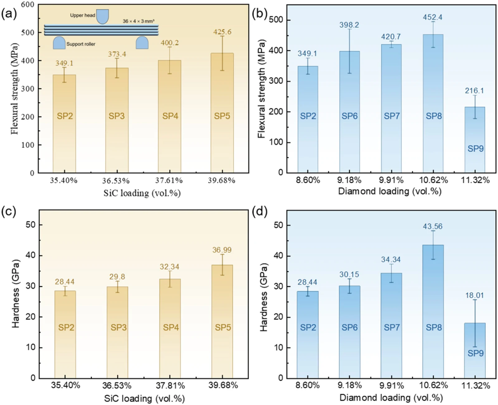
The optimally formulated SP8, sintered under the fast-heating protocol, delivered:
- Flexural strength: 452.4 ± ~55 MPa (7 bars, 36 × 4 × 3 mm, 30 mm span)
- Vickers hardness: 43.56 GPa
- Density: 3.14 g/cm³, open porosity 0.061–0.337%
- Residue silicon: 7.8 vol%
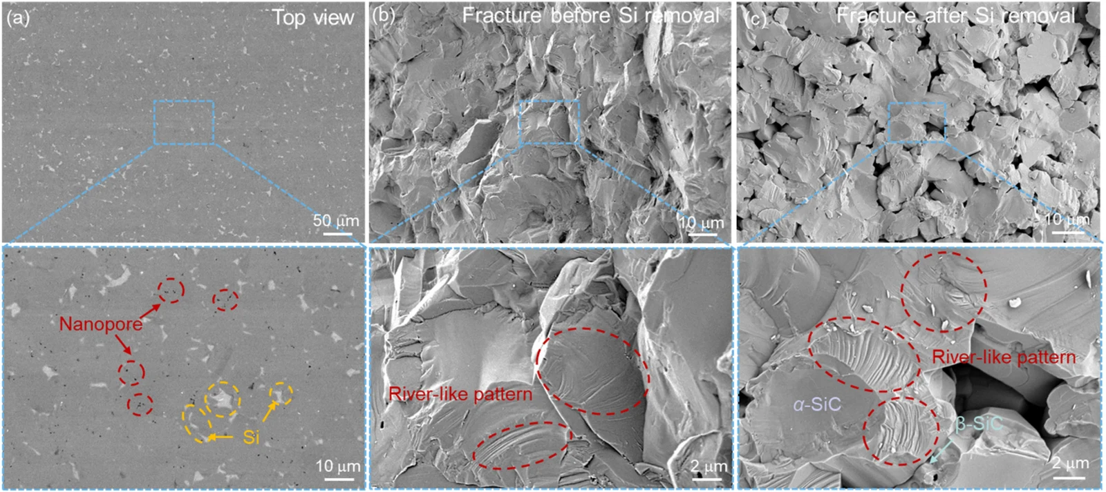
TEM and EBSD showed why the material is strong at the grain scale: secondary SiC grows epitaxially on the original α-SiC particles and bridges them into a continuous 3D network, so cracks are forced through the grains themselves — transgranular fracture with river-pattern markings — instead of skirting weak phase boundaries.
4. The mechanism: stress borrowed from tempered glass
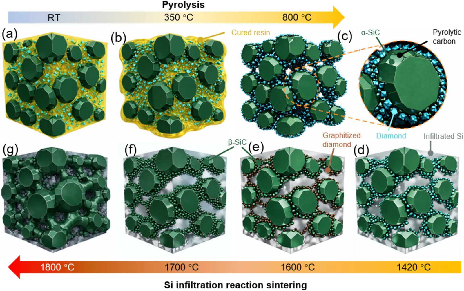
The two carbon sources react on different clocks. Resin-derived pyrolytic carbon is highly reactive and converts to SiC below 1500 °C, forming an early rigid skeleton. Diamond only graphitizes above ~1600 °C — and that transformation expands its volume substantially (density falls from 3.52 to 2.26 g/cm³). Under fast heating (4 °C/min), the early skeleton is already rigid when graphitization kicks in, so the expansion is trapped: it cannot expand the part, so it builds a huge compressive residual stress in the near-surface regions. XRD (sin²ψ method) measured −934 ± 112 MPa at the surface of SP8.
That is a stress profile, not just a stress level: surface in compression, core inferred to be in tension — the same architecture that makes chemically tempered glass hard to break. Under bending, ceramics fail from the tension side; a pre-compressed surface must first be "unloaded" before the applied tensile stress can open cracks. The compressive skin also closes surface microcracks, attacking failure at its usual starting point.
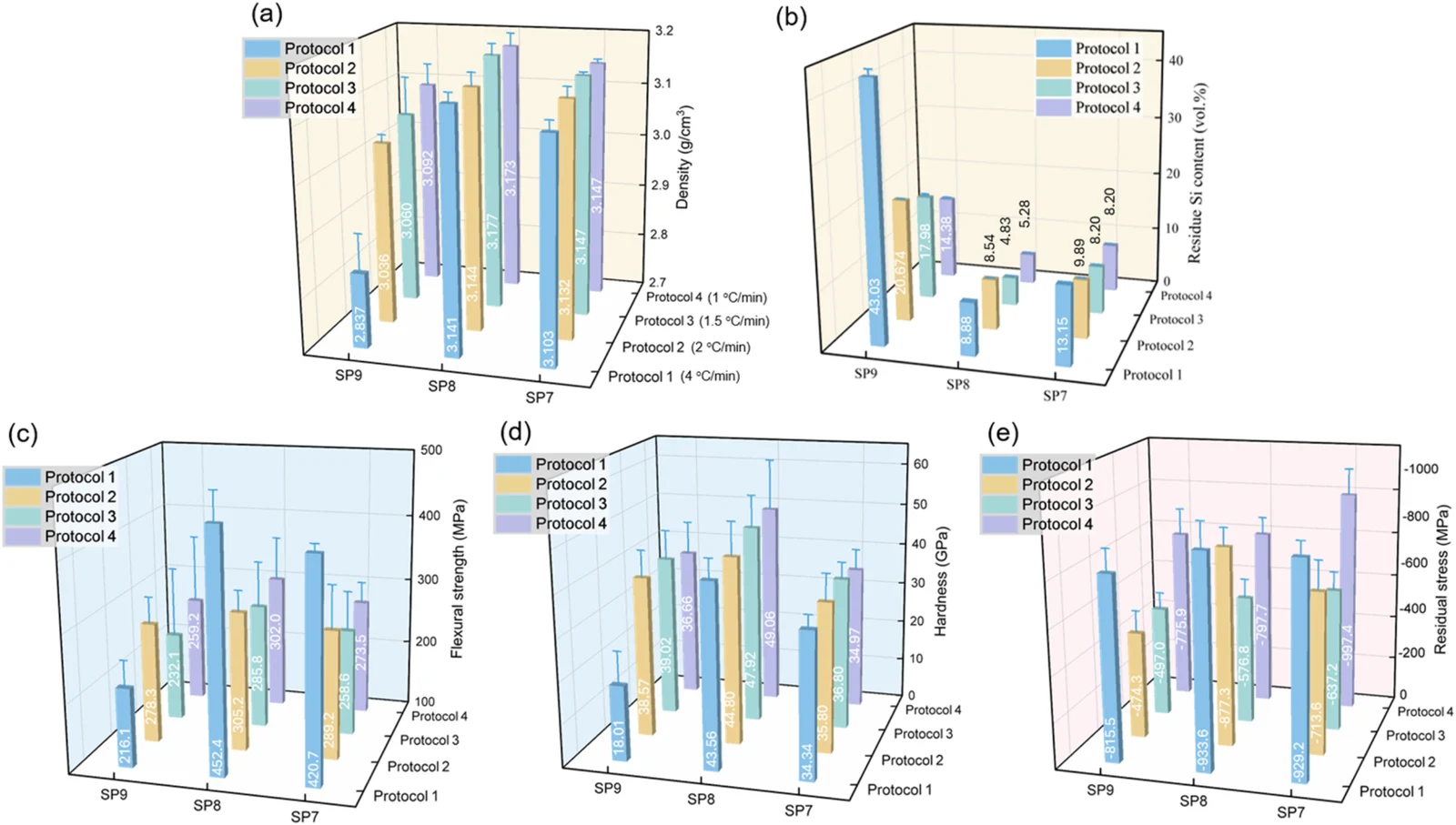
This produces the paper's most counterintuitive result. Slow the heating from 4 to 1 °C/min and density rises (3.141 → 3.173 g/cm³ for SP8) — yet flexural strength falls from 452.4 to 302.0 MPa. The reason: slow heating gives silicon time to fully infiltrate before the skeleton rigidifies, the diamond's expansion is gradually relieved, and the compressive skin never develops. More density, less strength. For a process engineer, that inverts the usual instinct: here, the faster ramp wins.
The authors also note this stress state is the opposite of conventional RBSC, where silicon solidification puts the SiC skeleton in tension — a state that preloads exactly the direction in which ceramics are weakest. Reversing it is the paper's core idea.
5. Where this sits among 3D-printed RBSC
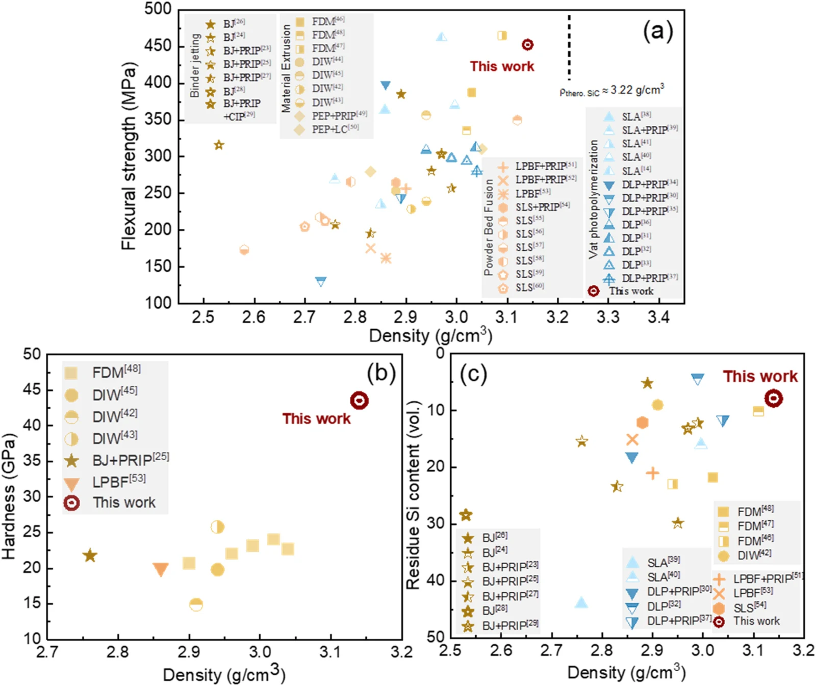
Plotted against dozens of prior 3D-printing RBSC studies, the result stands out on two axes: hardness (43.56 GPa is the highest in the comparison) and density achieved without phenolic-resin re-impregnation or cold isostatic pressing — post-treatments many competing studies needed. Flexural strength sits at the top of the vat-photopolymerization band. For context, earlier diamond-based DLP work cited in the paper reached 312 MPa; the stress-engineering step is what adds the last ~140 MPa.
6. What the study does not show
- The tensile core is inferred, not measured. XRD measured the surface compressive stress only; the center tension follows from overall stress balance and Raman mapping, not from direct measurement through the thickness.
- Fast heating is a narrow window. The optimal protocol (4 °C/min to 1800 °C) depends on the resin's pyrolysis behaviour and the preform's pore structure. A different geometry or wall thickness may shift where the "armor" forms — and SP9 shows how badly over-diamond formulations fail under the same protocol.
- Seven bars per condition. Flexural strength of ceramics scatters; the reported means come from seven specimens each.
- No thermal shock, oxidation, fatigue or fracture-toughness data. Compressive surface layers help strength under bending, but the paper does not test the behaviours that matter for a mirror or a semiconductor chuck in service.
- One powder system. Results are specific to this SiC + submicron-diamond pairing (D50 11.87 µm / 0.73 µm) and this resin chemistry.
7. What it means for SiC production
Two takeaways survive the caveats. First, the carbon source is not a commodity ingredient — choosing one that is UV-transparent, non-shrinking and size-graded against the ceramic powder fixed the slurry, the infiltration and the microstructure in a single move. Second, residual stress is a design variable. The same printer, the same powder, the same temperature, only the heating rate changed, and strength moved by 150 MPa because the stress distribution changed.
For labs working on RBSC — optical, semiconductor, aerospace — this was demonstrated on ADT's DLP Ceramic 3D Printer for Industry (Ceram-D-F192 class, 192 × 108 × 120 mm build, 3840 × 2160 resolution). The workflow is conventional DLP plus a furnace; no infiltration-exclusive equipment, no post-processing pressure step.
Source: Qu R, Hao W, Hao W, Li Z, Zhang G, Jin P, Zhu P, Wang F, Zhang J, Sun S, Xu Y. Digital light processing of high-strength reaction-bonded SiC with a tempered-glass-like stress distribution. Additive Manufacturing 129 (2026) 105390. doi:10.1016/j.addma.2026.105390. Figures reproduced from the cited article for discussion.