
Zirconia ceramics, known for their exceptional flexural strength and wear resistance, also exhibit excellent biocompatibility and aesthetically pleasing translucency, making them the preferred material for dental applications. However, traditional crown manufacturing methods often suffer from insufficient accuracy and poor adaptability. Ceramic 3D printing, with its layer-by-layer manufacturing approach, can overcome these shortcomings. Recently, Professor Li Ping from Guangzhou Medical University led a team to publish a study titled “Zirconia crowns manufactured using digital light processing: Effects of build angle and layer thickness on the accuracy” in the Journal of Dentistry. The study explored the effects of build angle and layer thickness on the accuracy and precision of zirconia crowns manufactured through ceramic 3D printing, ultimately identifying optimal build angles and layer thicknesses.

Original link: https://doi.org/10.1016/j.jdent.2024.105359
Official website products: https://www.adventure-tech.cn/Products.html
Previous studies have shown that layer thickness significantly affects printing accuracy, time, and material consumption in DLP ceramic 3d printing. For example, a layer thickness of 100 μm can reduce printing time while maintaining accuracy. Crowns printed at 50 μm and 100 μm layer thicknesses have similar clinical accuracy, but the latter improves manufacturing efficiency. However, although research has focused on the impact of layer thickness on various printed objects (such as complete dentures and resin tooth models), no study has yet explored the effects of build angle and layer thickness on the accuracy of DLP-printed zirconia crowns.
This study experimentally investigated the effects of three different build angles and two layer thicknesses on the accuracy of DLP-printed zirconia single crowns and proposed the null hypothesis: that build angle and layer thickness have no significant impact on printing accuracy.
The following sections outline the research methods and data of the article:
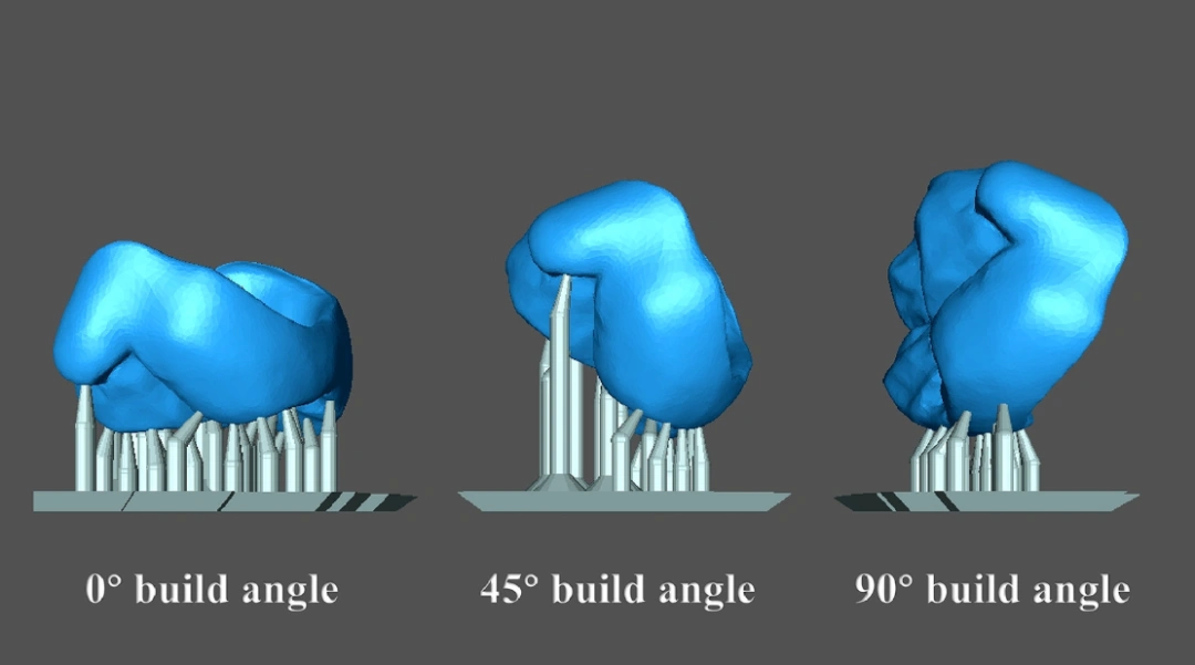
△ Figure 1, samples at three build angles (0°, 45° and 90°) and the corresponding automatically generated support structures.
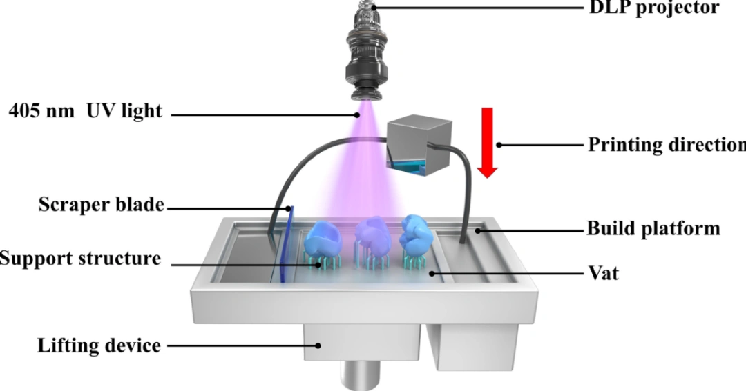
△Figure 2, schematic diagram of DLP printing technology from top to bottom.
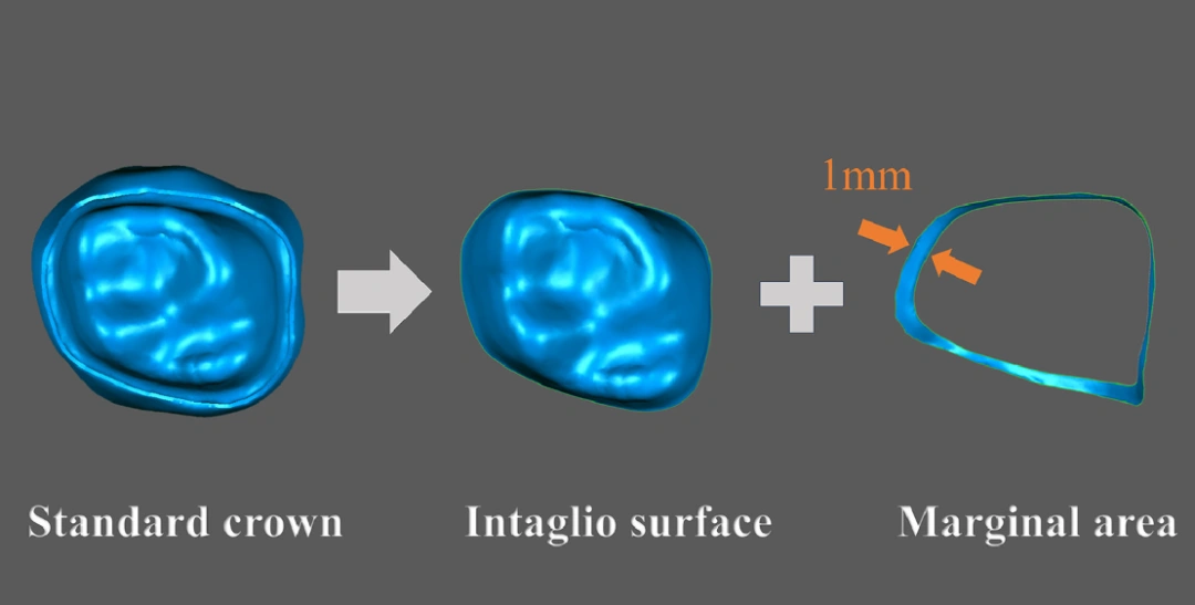
△Figure 3, STL model of standard first molar crown sliced into intaglio surface and edge areas.
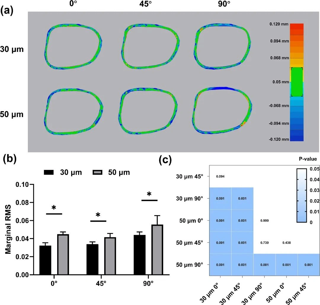
△ Figure 4, Margin fidelity evaluation of DLP samples printed at different build angles and layer thicknesses. (a) Color map represents the fidelity of DLP-printed crown margins with a tolerance of ± 0.05 mm and a maximum acceptable deviation of ± 0.120 mm; (b) Margin RMS value - asterisks indicate significant differences (* p < 0.05); (c) Heat map depicts Tukey multiple comparisons of margin area fidelity analysis between all groups. Blue boxes indicate statistically significant differences (p < 0.05), while white boxes indicate no statistical differences (p > 0.05).
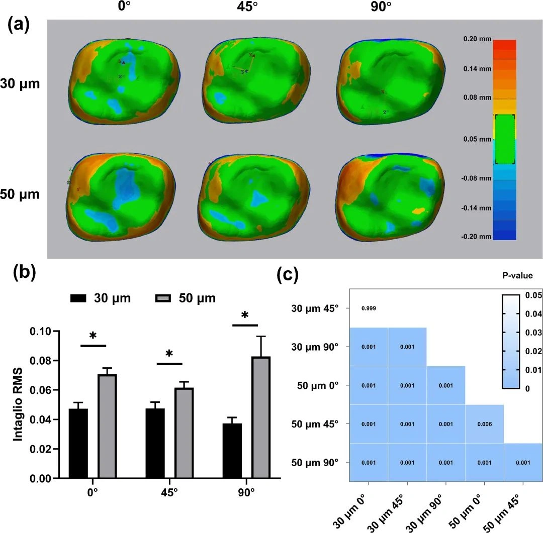
△Figure 5. Evaluation of gravure surface fidelity of DLP samples printed at different build angles and layer thicknesses. (a) Color map showing the fidelity of the crown gravure surface printed by DLP with a tolerance of ± 0.05 mm and a maximum acceptable deviation of ± 0.20 mm; (b) gravure RMS value. Asterisks indicate significant differences (* p < 0.05); (c) Heat map showing Tukey multiple comparisons of gravure surface fidelity analysis among all groups. Blue boxes indicate statistically significant differences ( p < 0.05), and white boxes indicate no statistical differences ( p > 0.05).
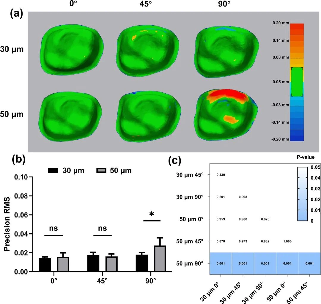
△ Figure 6, Accuracy evaluation of DLP samples printed at different build angles and layer thicknesses. (a) Color map represents the accuracy of the crown gravure and edge regions of DLP printing, with a tolerance of ±0.05 mm and a maximum acceptable deviation of ±0.20 mm; (b) Accuracy RMS value. Asterisks indicate significant differences (* p < 0.05), and "ns" indicates no significant difference; (c) Heat map depicts Tukey multiple comparisons of the gravure and edge region accuracy analysis between all groups. Blue boxes indicate statistically significant differences (p < 0.05), and white boxes indicate no statistical differences (p > 0.05).
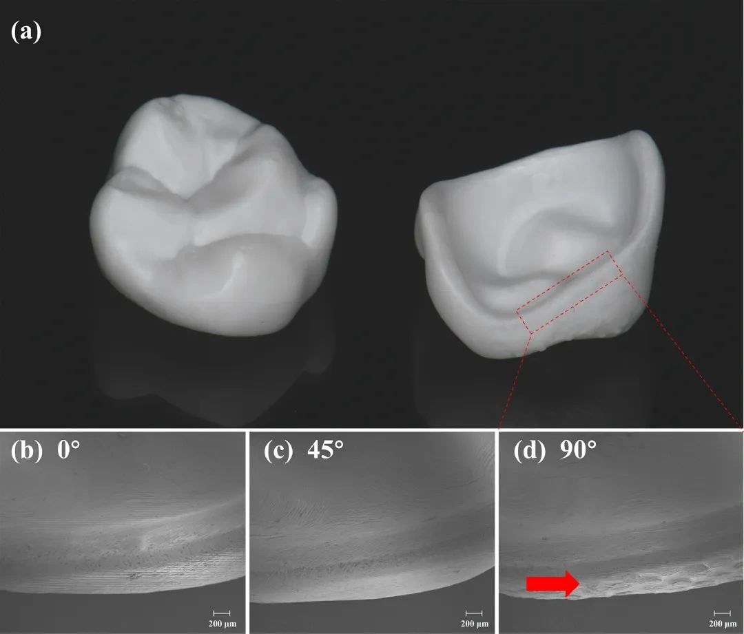
△ Figure 7, DLP printed zirconia crown and representative SEM images after 30 times magnification. (a) Sample overview; (b) 0° angle - defect-free edge; (c) 45° angle - defect-free edge; (d) 90° angle - defect after support removal (red arrow).
Conclusion
The results indicate that build angle and layer thickness significantly affect the accuracy of zirconia crowns printed using DLP technology. Crowns printed with a layer thickness of 30 μm demonstrated higher accuracy than those printed with 50 μm. To ensure marginal precision, it is recommended to use a layer thickness of 30 μm and build angles of 0° or 45° when printing zirconia crowns via DLP.
This study explored build angles and layer thicknesses as continuous variables, and the limited selection of representative angles and layer thicknesses may be a limitation. Additionally, the study used mandibular first molars for crown restorations, and the findings may not be applicable to other tooth conditions or multi-unit bridge restorations.